WAV player based on STM32 microcontroller
Some time ago I received a NUCLEO-STM32H743ZI board.
It features one of the high-end H7 ST microcontrollers - and it’s quite a beast indeed!
480MHz CPU, 1MB of RAM and a rich set of peripherals including CAN interface, LCD-TFT driver, DAC and Ethernet.
So what do I do with all this power?
I built a WAV file player.
…
I know, not really impressive. But keep in mind that this was done mainly as an exercise and a way to get familiar with the microcontroller. The software makes use of onboard 12-bit DAC, SPI peripheral (to communicate with an SD card), DMA and three HW timers.
Storage
A second of 8-bit PCM 2-channel audio uses ~88kB of memory. Thus, storing the entirety of an uncompressed song in the internal flash is not possible. As the storage medium I used a microSD card connected via an SPI adapter. A better solution would be to use the MCU’s internal SD-MMC controller, but I didn’t have a SD socket laying around, so i chose the SPI adapter instead.
Remember: Not all SD cards support the SPI mode! Kingston cards seem to not work most of the time based on my and others’ experience.
The SD cards usually are formatted with FAT32. To manage files i used the FatFs filesystem and kiwih’s SPI SD driver that handles the hardware layer.
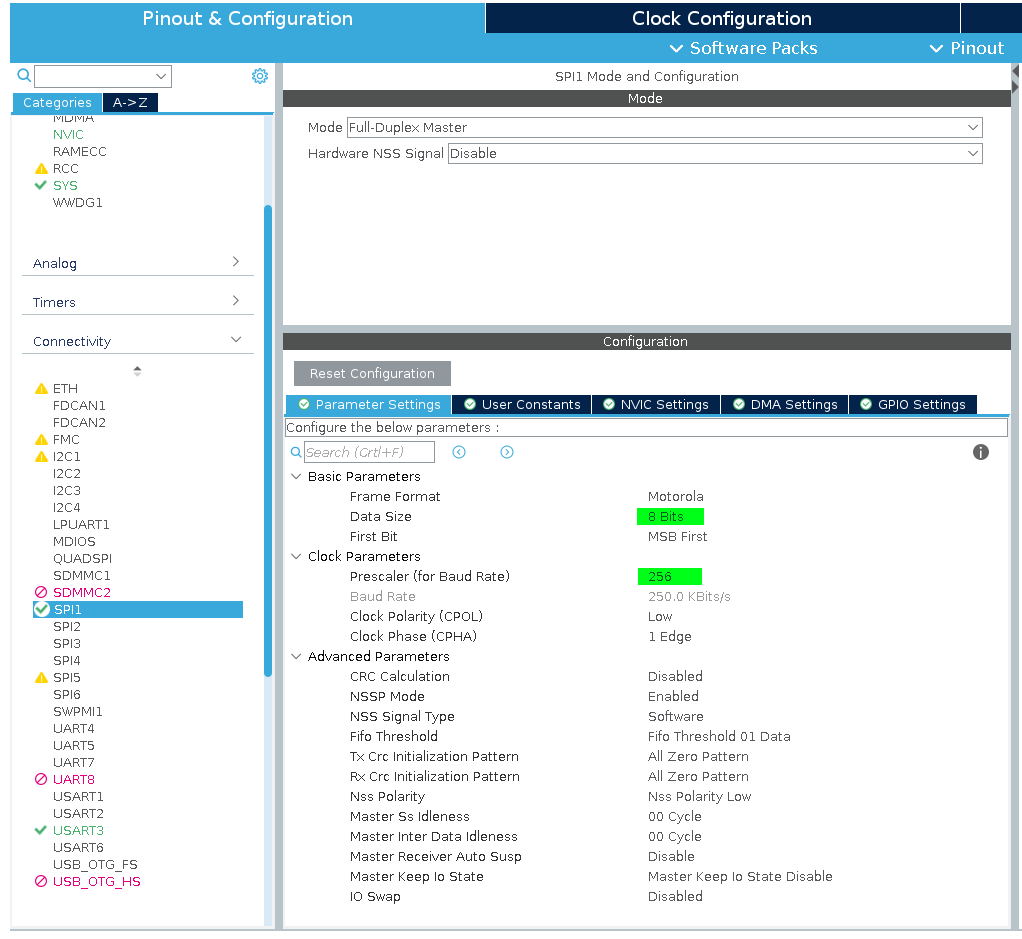
So let’s start, shall we? Open CubeMX, create new project and go to SPI settings. Set Data size to 8 bits. Set prescaler so you get around 250Kbit/s baudrate. It doesn’t have to be exactly that value, but it can’t be too big. The SD card in SPI mode must first be initialized in low speed mode, and only then we can switch to high speed. CubeMX will set up default MISO, MOSI and SCK pins for you. You can change the pins used by SPI by selecting another supported pin from the pinout view and setting it as SPI pin. You also need to set one GPIO pin as output - it will be used as the CS pin.
When you’re done go to Middleware>FATFS tab and enable FATFS in User-Defined mode. You can also enable USE_LFN if you want to be able to use filenames longer than 13 characters.
Generate project. Grab kiwih’s SPI driver and put user_diskio_spi.c and user_diskio_spi.h into your source code. In user_diskio.c make each USER function call corresponding function from the SPI driver.
For example:
DRESULT USER_write (
    BYTE pdrv,          /* Physical drive nmuber to identify the drive */
    const BYTE *buff,   /* Data to be written */
    DWORD sector,       /* Sector address in LBA */
    UINT count          /* Number of sectors to write */
)
{
  /* USER CODE BEGIN WRITE */
  /* USER CODE HERE */
    return USER_SPI_write(pdrv, buff, sector, count);
  /* USER CODE END WRITE */
}
In user_diskio.c You need to #define the handle to SPI peripheral (SD_SPI_HANDLE) and the port (SD_CS_GPIO_Port) and pin (SD_CS_GPIO_Pin) used by the CS pin. In the same file you need to change lines 38 and 39 and set the prescalers to get approximately the listed speeds. In my case SPI was clocked at 64MHz, so I set the prescalers to 256 and 16 to get 250kbps and 4Mbps accordingly.
#define FCLK_SLOW() { MODIFY_REG(SD_SPI_HANDLE.Instance->CR1, SPI_BAUDRATEPRESCALER_256, SPI_BAUDRATEPRESCALER_256); }	/* Set SCLK = slow, approx 280 KBits/s*/
#define FCLK_FAST() { MODIFY_REG(SD_SPI_HANDLE.Instance->CR1, SPI_BAUDRATEPRESCALER_256, SPI_BAUDRATEPRESCALER_16); }	/* Set SCLK = fast, approx 4.5 MBits/s */
And here’s something very important that cost me an hour of debugging later in the project
The SPI registers of the H7 family MCU’s are a bit different. While in other ST microcontrollers prescalers are set in the CR1 register, in H7 they’re set in CFG1 register. So if you’re using a H7 change the above two lines and replace CR1 with CFG1. Then you’re good to go.
Now the driver and filesystem should be configured. You can find more detailed instructions of setting up the driver in the blog post by its author himself.
Generating an audio signal
Audio is an analog signal and we need a way to generate one. As far as I’m aware, there are three ways to do so:
- Generate signal using PWM. The advantage of this approach is that it can be used even with microcontrollers that don’t have any kind of analog output. It uses PWM (usually generated by a hardware timer) to generate pseudo-analog signal. The sound quality - as expected - is worse compared to a DAC.
- External Digital to Analog Converter. On the market you can find various external DACs. Those suited for audio playback usually offer at least 16-bit precision stereo output and an I2S interface. This is the best way to get a good sound quality from the microcontroller, especially since our H7 has hardware support for I2S. Those converters are a bit costly though, and I wanted to only use stuff I had already had.
- Internal DAC. The STM32H743 features a 12-bit internal DAC.
In this project I’m going to use the internal DAC with 8-bit precision. The player will use double buffering, which uses DMA timed by a hardware timer to load consecutive samples into the DAC register, while at the same time the CPU reads data from storage to another buffer. When DMA transfer finishes, the buffers are swapped and the process starts again.
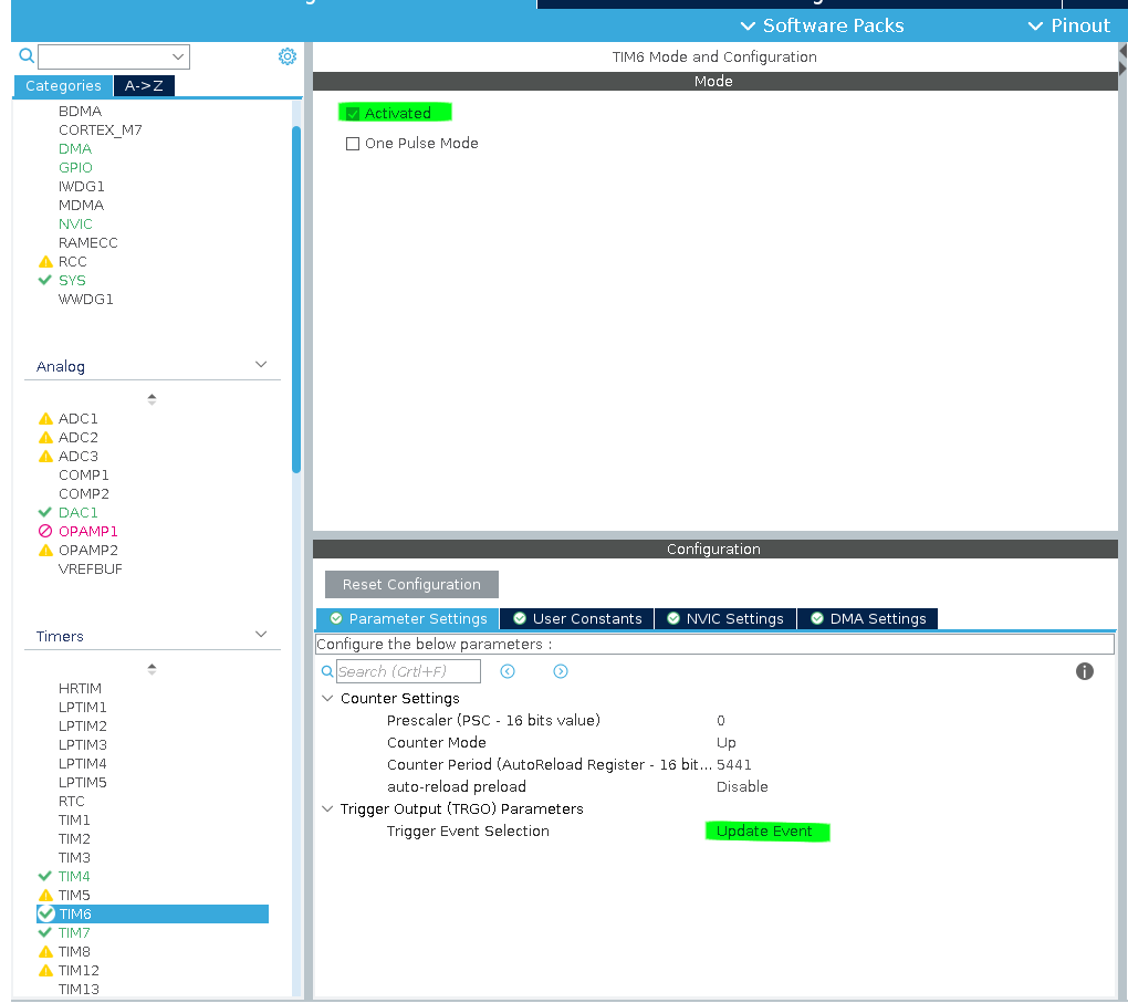
Let’s start with configuring the timer. In CubeMX select the timer you want to use and activate it (For some timers you need to select a clock source - use internal clock). Set Trigger Event Selection to Update Event. You don’t need to set counter period yet - we’ll do it later in software.
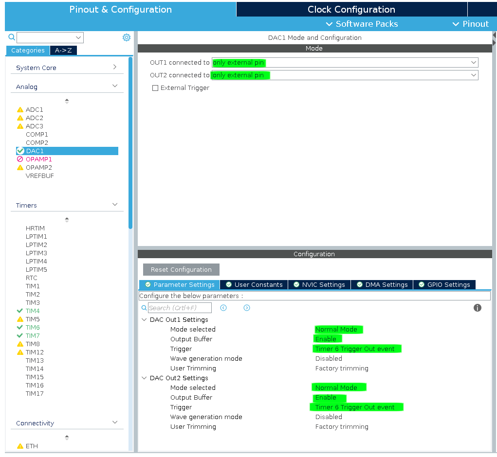
Next, set up the DAC. Set both outputs to external pin, normal mode. Select timer you set up earlier as the trigger. I also recommend enabling buffers for outputs.
Next we’ll set the DMA. Go to DMA tab and add new request. Select DAC1_CH1 from the list. Click on the newly created request and set mode to Normal and the data width to Half Word. Finally, go to NVIC tab and enable the DAC interrupt. In my case it’s named “TIM6 global interrupt, DAC1_CH1 and DAC1_CH2 underrun error interrupts”.
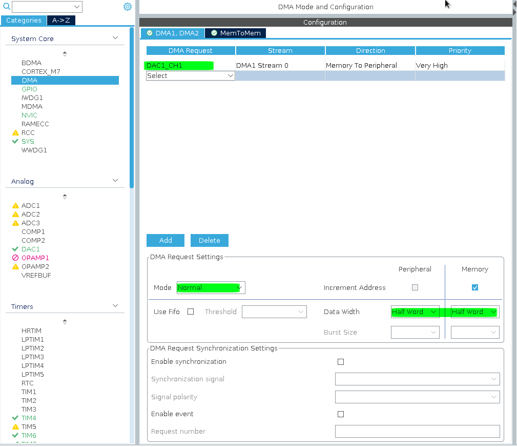
Wait, why are we only setting DAC1_CH1 transfer? We want to play on both channels! Also, half-word data width? Shouldn’t it be bytes since we’re using 8-bit samples? Don’t worry - those settings are correct and I will explain why in a moment.
To play the audio file we need to know a few things: the sample rate, sample format, number of channels and data length. All of this information can be found in the header of a WAV file. If you want to learn more about the WAV format, you can read about it here. We need to extract relevant data from the fmt chunk. For the sake of simlicity we are going to support only 8-bit integer samples, max 2 channels and no extensions.
Let’s write a simple wav header parser! Create files wavparser.h and wavparser.c. In wavparser.h define a struct for wave data and define the parsing function.
#include <stdint.h>
#include <stdio.h>

typedef enum {
    WAVE_FORMAT_PCM = 1,
    WAVE_FORMAT_IEEE_FLOAT = 3,
    WAVE_FORMAT_ALAW = 6,
    WAVE_FORMAT_MULAW = 7,
    WAVE_FORMAT_EXTENSIBLE = 0xFFFE,
} WaveFormat;

typedef struct {
    uint32_t fmt_chunk_size;
    WaveFormat format;
    uint16_t n_channels;
    uint32_t sample_rate;
    uint16_t bits_per_sample;
    uint32_t data_size;
} WavData;

int parse_wav_header(const uint8_t* buffer, WavData* data);
In wavparser.c we put the implementation of our parsing function.
#include <string.h>
#include <wavparser.h>

//Utility function interpreting 4 bytes as 32-bit unsigned int
uint32_t get_uint32(const uint8_t* buf)
{
    int res = buf[0] + (buf[1] << 8) + (buf[2] << 16) + (buf[3] << 24);
    return res;
}

//Utility function interpreting 2 bytes as 16-bit unsigned int
uint16_t get_uint16(const uint8_t* buf)
{
    int res = buf[0] + (buf[1] << 8);
    return res;
}

int parse_wav_header(const uint8_t* buffer, WavData* data)
{
    //Check for WAVE file IDs to make sure we're parsing a valid WAV file
    int r = strncmp((const char*)buffer, "RIFF", 4);
    if (r != 0) {
        return -1;
    }

    r = strncmp((const char*)&buffer[8], "WAVE", 4);
    if (r != 0) {
        return -1;
    }

    uint32_t file_size = get_uint32(&buffer[4]);

    r = strncmp((const char*)&buffer[12], "fmt", 3);
    if (r != 0) {
        return -1;
    }

    //Save data to the WavData struct.
    data->fmt_chunk_size = get_uint32(&buffer[16]);
    data->format = get_uint16(&buffer[20]);
    data->n_channels = get_uint16(&buffer[22]);
    data->sample_rate = get_uint32(&buffer[24]);
    data->bits_per_sample = get_uint16(&buffer[34]);
    data->data_size = get_uint32(&buffer[40]);

    return 1;
}
I put the implementation of audio player into audio_player.c and audio_player.h files. In the header file we define enums for player status and result of loading file. We also declare functions that we want to expose to the rest of the program.
#include "main.h"
#include <fatfs.h>
#include <stdint.h>

enum PlayerStates {
    PSTATUS_PLAYING,
    PSTATUS_STOPPED,
    PSTATUS_READY,
};

enum PlayerLoadResult {
    PLAYER_OK = 1,
    PLAYER_UNSUPP_CHNL = 0,
    PLAYER_ERR_GENERIC = -1,
    PLAYER_UNSUPP_FMT = -2,
    PLAYER_UNSUPP_SMPLRATE = -3,
    PLAYER_UNSUPP_BITRATE = -4,
    PLAYER_PARSE_ERR = -5,
    PLAYER_FS_ERROR = -6,
};

void player_init(DAC_HandleTypeDef* dac_handle, TIM_HandleTypeDef* timer_handle, uint32_t timer_frequency);
int player_loadfile(FILINFO fileinfo);
void player_play();
void player_stop();
enum PlayerStates player_get_state();
double player_get_progress();
void player_dac_dma_callback();
Let’s head over to audio_player.c file and start writing the implementation. Let’s start by declaring some constants and static variables.
#include <audio_player.h>
#include <ff.h>
#include <stdint.h>
#include <stm32h7xx_hal_dac.h>
#include <stm32h7xx_hal_dac_ex.h>
#include <string.h>
#include <wavparser.h>

#define DMA_MAX_TRANSFER 65535 // Max number of bytes we can transfer in DMA request
#define BUFFER_SIZE 2048       // Audio buffer size

static uint32_t data_len = 0;  // Length of file
static uint32_t data_pos = 0;  // Number of bytes loaded from SD
static uint32_t playing_pos = 0; // Number of bytes already played
static uint32_t bytes_to_transfer = 0; // Number of bytes to transfer in dma request
static uint16_t n_channels = 2; // Number of audio channels in file

// Buffers
static uint8_t buf1[BUFFER_SIZE];
static uint8_t buf2[BUFFER_SIZE];

//Pointers to buffers
static uint8_t* playing_buffer = buf1;
static uint8_t* reading_buffer = buf2;

//Player status
static enum PlayerStates player_state = PSTATUS_STOPPED;

//Peripheral handles
static DAC_HandleTypeDef* hdac;
static TIM_HandleTypeDef* htim;

static FIL current_file; //Handle to loaded file
static uint32_t timer_freq = 0; //Timer frequency
The player_init function should be called once. We pass handles to required peripherals and timer clock frequency. The clock frequency will be used to calculate auto-reload value so that timer can trigger DAC on intervals equal to the audio file’s sampling rate.
void reset()
{
    data_len = 0;
    data_pos = 0;
    playing_pos = 0;
    bytes_to_transfer = 0;
    n_channels = 2;
}

void player_init(DAC_HandleTypeDef* dac_handle, TIM_HandleTypeDef* timer_handle, uint32_t timer_frequency)
{
    reset();
    hdac = dac_handle;
    htim = timer_handle;
    timer_freq = timer_frequency;

    HAL_GPIO_TogglePin(GPIOB, GPIO_PIN_0); //For debugging purposes
}
Let’s add parse_wav function that uses our previously implemented WAV header parser to extract the data we need to play the file. It’s quite long with all the error handling but we want the filesystem errors to be distinguished from other kinds of errors. Non-FS error can be handled by simply not loading the file. Filesystem errors are critical and require re-mounting of the filesystem or restarting the device.
int parse_wav(WavData* wav_data)
{
FRESULT fres = FR_OK;
uint8_t buffer[44];
unsigned int bytes_read = 0;
fres = f_read(¤t_file, buffer, 44, &bytes_read);
if (fres != FR_OK) {
return PLAYER_FS_ERROR;
}
if (bytes_read != 44) {
return PLAYER_PARSE_ERR;
}
int res = parse_wav_header(buffer, wav_data);
if (res != 1) {
return PLAYER_PARSE_ERR;
}
//seek to the start of PCM data
fres = f_lseek(¤t_file, 20 + wav_data->fmt_chunk_size);
if (fres != FR_OK) {
return PLAYER_FS_ERROR;
}
fres = f_read(¤t_file, buffer, 4, &bytes_read);
if (fres != FR_OK) {
return PLAYER_FS_ERROR;
}
if (bytes_read != 4) {
return PLAYER_PARSE_ERR;
}
//make sure it's a data chunk - we don't support any extensions for now
int r = strncmp((const char*)buffer, "data", 4);
if (r != 0) {
return PLAYER_PARSE_ERR;
}
return PLAYER_OK;
}The player_loadfile function takes FATFS’s FILEINFO structure containing data about the file we want to open. It calls the wav parser, sets up the DAC timer with correct frequency and fills up the buffers.
int player_loadfile(FILINFO fileinfo)
{
reset();
FRESULT fres = FR_OK;
//Opening the file
fres = f_open(¤t_file, fileinfo.fname, FA_READ);
if (fres != FR_OK) {
return PLAYER_FS_ERROR;
}
//Parsing wav header
WavData wav_data;
int r = parse_wav(&wav_data);
if (r != PLAYER_OK) {
return r;
}
// ...
// Here i skipped some checks,
// for instance check if file has supported format and samplerate
// ...
n_channels = wav_data.n_channels;
data_len = wav_data.data_size;
//Setting up the timer frequency
htim->Instance->ARR = ((timer_freq / wav_data.sample_rate) - 1);
//Filling the buffers
//The order here is important!
fres = load_bytes(playing_buffer, BUFFER_SIZE);
if (fres != FR_OK) {
return PLAYER_FS_ERROR;
}
fres = load_bytes(reading_buffer, BUFFER_SIZE);
if (fres != FR_OK) {
return PLAYER_FS_ERROR;
}
player_state = PSTATUS_READY;
return 1;
}Now we need to implement the load_bytes function. For some reason I get filesystem errors when trying to read more than 512 bytes from SD card in a single transfer. I am not sure if this is the issue with the SD card i got, FATFS, or the SPI driver. The workaround is to read data in 512b chunks. When loading from mono file we need to duplicate the samples so that the same sample plays in both channels.
int load_bytes_stereo(uint8_t* buffer, uint32_t buflen)
{
unsigned int bytes_read_total = 0;
for (int i = 0; i < buflen; i += 512) {
unsigned int bytes_r = 0;
FRESULT res = f_read(¤t_file, &buffer[i], 512, &bytes_r);
if (res != FR_OK) {
return res;
}
if (bytes_r == 0) {
break;
}
bytes_read_total += bytes_r;
}
data_pos += bytes_read_total;
return FR_OK;
}
int load_bytes_mono(uint8_t* buffer, uint32_t buflen)
{
uint8_t temp_buf[buflen / 2];
unsigned int bytes_read_total = 0;
for (int i = 0; i < buflen / 2; i += 512) {
unsigned int bytes_r = 0;
FRESULT res = f_read(¤t_file, &temp_buf[i], 512, &bytes_r);
if (res != FR_OK) {
return res;
}
if (bytes_r == 0) {
break;
}
bytes_read_total += bytes_r;
}
//duplicate the samples
for (int i = 0; i < buflen / 2; i++) {
buffer[2 * i] = temp_buf[i];
buffer[(2 * i) + 1] = temp_buf[i];
}
data_pos += bytes_read_total;
return FR_OK;
}
int load_bytes(uint8_t* buffer, uint32_t buflen)
{
if (n_channels == 2) {
return load_bytes_stereo(buffer, buflen);
}
return load_bytes_mono(buffer, buflen);
}Now it’s time for player_start and player_stop functions. To start playing file, we need to start the DAC timer and DMA transfer.
HAL_DACEx_DualStart_DMA is a function from the extended HAL module driver. It allows us to transfer samples to both DAC channels in a single DMA request.
Instead of transfering data to data holding registers corresponding to specific channels (DAC_DHR8R1 and DAC_DHR8R2) this function instead sets the destination
address to DAC_DHR8RD dual DAC register, which can hold data for both channels.
This allows us to transfer two 8-bit samples in one DMA write cycle.
This is why we set data width to half-word earlier - half word equals two bytes and we want to transfer two samples at once.
Why is the purpose of the second argument then? It just sets the callbacks we want to use.
If you set the channel as channel 1, DMA will call callbacks for channel 1
(like HAL_DAC_ConvCpltCallbackCh1) and if you set channel 2 - corresponding callbacks for channel 2.
void player_play()
{
    if (player_state != PSTATUS_READY) {
        return;
    }

    uint32_t transfer_size = min(data_pos, BUFFER_SIZE);

    HAL_DACEx_DualStart_DMA(hdac, DAC_CHANNEL_1, (uint32_t*)playing_buffer, transfer_size / 2, DAC_ALIGN_8B_R);
    HAL_TIM_Base_Start(htim); // DAC Timer
    bytes_to_transfer = transfer_size;

    player_state = PSTATUS_PLAYING;
}
To stop playback we simply stop the DMA transfer and DAC timer. Don’t forget to also close the file!
void player_stop()
{
if (player_state == PSTATUS_STOPPED) {
return;
}
HAL_DAC_Stop_DMA(hdac, DAC_CHANNEL_1);
HAL_TIM_Base_Stop(htim); // DAC Timer
player_state = PSTATUS_STOPPED;
HAL_GPIO_TogglePin(GPIOB, GPIO_PIN_14);
f_close(¤t_file);
}Here comes the most important part. The DMA transfer complete callback. When we finish playing contents of the buffer, we get the transfer complete callback. In the callback we need to do the following:
- Check position of file and stop the player if we already played the entirety of the file
- Swap pointers to playing buffer and reading buffer
- Start the DMA transfer from the playing buffer
- Read new samples into the reading buffer.
This way playing samples from the playing buffer and loading samples into the reading buffer can be done at the same time.
void player_dac_dma_callback()
{
    if (player_state == PSTATUS_STOPPED) {
        return;
    }

    //swap buffers
    uint8_t* temp = playing_buffer;
    playing_buffer = reading_buffer;
    reading_buffer = temp;

    HAL_GPIO_TogglePin(GPIOB, GPIO_PIN_0); //for debug purposes
    HAL_GPIO_TogglePin(GPIOE, GPIO_PIN_1);

    //Because we duplicate samples in mono mode we need to shift the position by half of bytes transferred
    //Otherwise the playback would stop in the middle of the file
    if (n_channels == 1) {
        playing_pos += bytes_to_transfer / 2;
    } else {
        playing_pos += bytes_to_transfer;
    }

    //Check stop condition
    if (playing_pos >= data_len - 1) {
        player_stop();
        return;
    }

    uint32_t bytes_left = data_len - playing_pos;
    uint32_t transfer_size = min(bytes_left, BUFFER_SIZE);

    //Start playing
    HAL_DACEx_DualStart_DMA(hdac, DAC_CHANNEL_1, (uint32_t*)playing_buffer, transfer_size / 2, DAC_ALIGN_8B_R);

    //Load new samples from file
    FRESULT fres = load_bytes(reading_buffer, BUFFER_SIZE);
    if (fres != FR_OK) {
        player_stop();
    }
    bytes_to_transfer = transfer_size;
}
The function player_dac_dma_callback needs to be called in the HAL_DAC_ConvCpltCallbackCh1 callback. Put this in your main.c:
void HAL_DAC_ConvCpltCallbackCh1(DAC_HandleTypeDef* hdac)
{
    player_dac_dma_callback();
}
Finally, let’s add functions to get the current state and position of the player:
enum PlayerStates player_get_state()
{
    return player_state;
}

double player_get_progress()
{
    if (player_state != PSTATUS_PLAYING) {
        return 0.0;
    }

    return (double)(playing_pos) / data_len;
}
User input
The device takes input from the user through a rotary encoder and a button. A hardware timer in encoder mode is used to receive input from the encoder. Using the timer instead of simple GPIO interrupts has an advantage of using the timer’s input filter to reduce the effect of contact bounce of the encoder. Encoder is used to select the file and the button is used to start and stop playback.
To configure timer in encoder mode you need to select Encoder mode from the Combined Channels list. I recommend setting input filter to 10 or higher for better debouncing. You also need to enable TIM global interrupt in the NVIC settings.
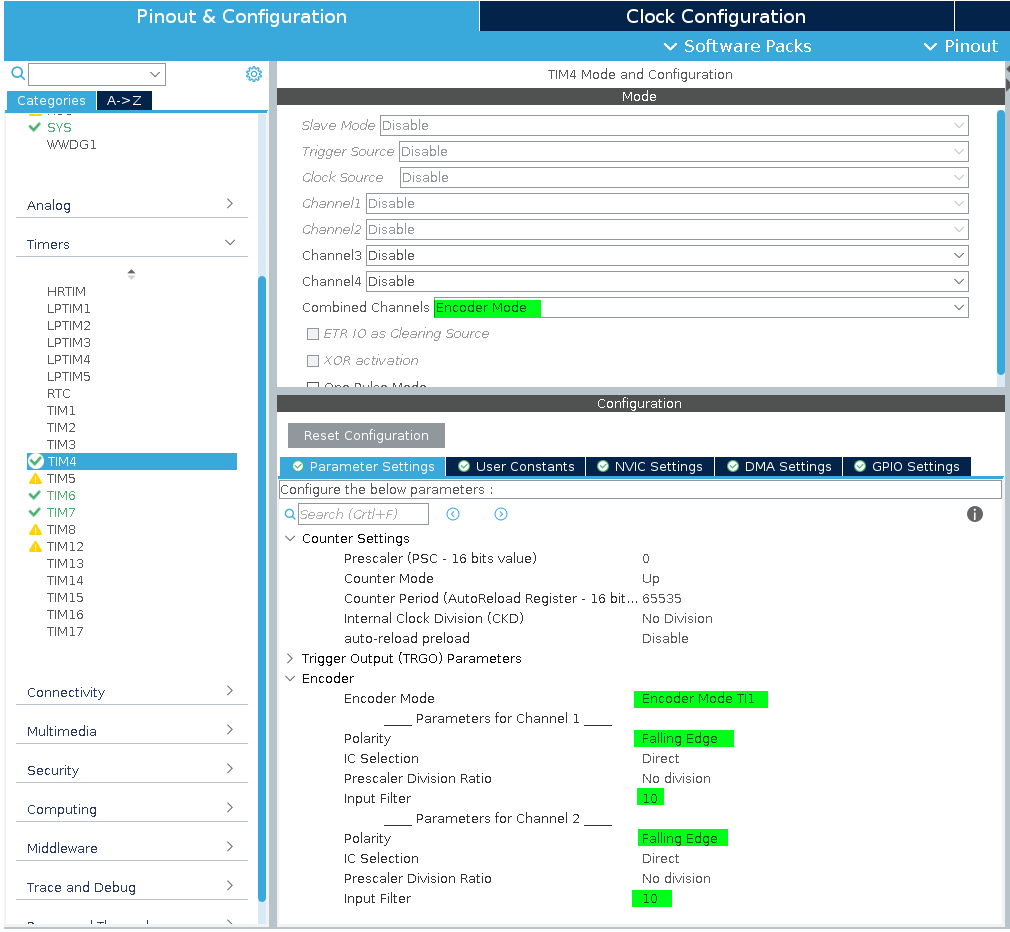
To configure the play/stop button just pick a pin and set it to GPIO_EXTI mode. Remember to enable the interrupt in NVIC settings.
To display data to the user I used HD44780 based 16x2 LCD display with my own simple driver. I am not going to describe it here in detail. See the lcd.c and lcd.h files in the project’s repository if you want to study or copy/paste the code.
Putting it all together
Time to write our main.c file. First, let’s list things we need to do:
- Mount the filesystem and enumerate WAV files
- Enable the user to select the file they want to play
- Display the name of the currently selected file on the display
- Display the progress bar of currently playing file
- Show errors on the LCD if any occur
First, let’s declare some global variables.
//Maximum of fileinfo objects we can store. H7 has plenty of RAM, so i went with 1024.
//Remember that fileinfo (especially with long filenames enabled) can take quite a lot of space!
#define max_files 1024

//Storing file information of wav files
static FILINFO files[max_files];

//used to check the encoder position
static uint16_t last_encoder_val = 0;

//index of currently selected file
static unsigned int selected_file = 0;

//Stores number of wav files found on the SD
static unsigned int file_count = 0;
Let’s start with two functions for displaying things on the LCD.
//Display text on the screen
void display_msg(const char* line_1, const char* line_2)
{
    LCD_clear();
    LCD_position(1, 1);
    LCD_write_text(line_1, strlen(line_1));
    LCD_position(1, 2);
    LCD_write_text(line_2, strlen(line_2));
}

//Display the name of currently selected file
//and progress bar in the second line
void display_ui()
{
    FILINFO file = files[selected_file];
    char line_1[16];
    char line_2[16];

    snprintf(line_1, 16, "%s", file.fname);

    if (player_get_state() == PSTATUS_PLAYING) {
        uint32_t filled_squares = (uint32_t)(player_get_progress() * 16);
        int i = 0;

        for (int i; i < 16; i++) {
            if (i <= filled_squares) {
                line_2[i] = '#';
            } else {
                line_2[i] = '-';
            }
        }
    } else {
        line_2[0] = '\0';
    }
    display_msg(line_1, line_2);
}
Then functions for mounting the filesystem and enumerating files in directory. To make this simple, we are going to just list the files from the FS root, without traversing subdirectories.
int mount_sd(FATFS* FatFs, DIR* dir)
{
    FRESULT fres = FR_OK; //Result after operations

    fres = f_mount(FatFs, "", 1); //1=mount now
    if (fres != FR_OK) {
        return 0;
    }

    fres = f_opendir(dir, "/");
    if (fres != FR_OK) {
        return 0;
    }

    return 1;
}

uint32_t enumerate_files(DIR* dir)
{
    FRESULT fres = FR_OK;

    file_count = 0;
    while (file_count < max_files) {
        FILINFO fnfo;
        fres = f_readdir(
            dir,
            &fnfo);

        if (fres != FR_OK || fnfo.fname[0] == 0) {
            break;
        }
        //filter to save only wav files
        char* pos = strstr(fnfo.fname, ".wav");

        if (pos == NULL) {
            continue;
        }

        files[file_count] = fnfo;
        file_count++;
    }

    return file_count;
}
Encoder handler checks the direction in which the encoder was turned and increments or decrements the selected_file index (also does bound checking).
You need to call handle_encoder_input in your TIM IRQ handler (in my case it’s TIM4_IRQHandler defined in stm32h7xx_it.c file).
void enc_up()
{
    selected_file++;
    if (selected_file >= file_count) {
        selected_file = file_count - 1;
    }
}

void enc_down()
{
    selected_file--;
    if (selected_file >= file_count) {
        selected_file = 0;
    }
}

void handle_encoder_input()
{
    int enc_val = TIM4->CNT;
    if (enc_val > last_encoder_val) {
        enc_up();
    } else if (enc_val < last_encoder_val) {
        enc_down();
    }

    last_encoder_val = enc_val;
    display_ui();
}
The button interrupt handler is very simple. If the player is playing, it stops the player. Otherwise, it calls the start_player function passing the file_info of currently selected file.
void button_handler()
{
    if (player_get_state() != PSTATUS_STOPPED) {
        player_stop();
        return;
    }

    start_player(files[selected_file]);
}

void HAL_GPIO_EXTI_Callback(uint16_t GPIO_Pin)
{
    if (GPIO_Pin == GPIO_PIN_13) {
        button_handler();
    }
}
The start_player function takes the file info and tries to load the file and play it. Here we do some error checking and display proper alerts on the LCD screen.
void start_player(FILINFO file)
{
    FRESULT fres = FR_OK;

    int result = player_loadfile(file);
    if (result != PLAYER_OK) {
        if (result == PLAYER_FS_ERROR) {
            display_msg("FS ERR RESTART", "DEVICE");
            Error_Handler();
        }
        display_msg("ERR OPEN.FILE", "UNSUPP FMT");
        return;
    }
    player_play();
    display_ui();
}
And finally, we define a delay function. This one is used by the LCD driver and needs to be passed to it. It uses hardware timer. Just select one in CubeMX, set prescaler to get 1Mhz clock rate and activate it.
void delay_us(uint16_t us)
{
    htim7.Instance->CNT = 0;
    while (htim7.Instance->CNT <= us) {
        //wait
    }
}
Finally, we write the main function.
int main(void)
{
    // ...
    // Auto-Generated initialization code
    // ...
    /* USER CODE BEGIN 2 */

    //Start timers
    HAL_TIM_Base_Start(&htim7); // Delay Timer
    HAL_TIM_Encoder_Start_IT(&htim4, TIM_CHANNEL_ALL);

    //Initialize LCD display
    LCD_init(delay_us);

    display_msg("WAV PLAYER", "loading...");

    //Initialize player
    //DAC timer is clocked at 240MHz
    player_init(&hdac1, &htim6, 240000000);

    FATFS FatFs; //Fatfs handle
    FIL fil; //File handle
    DIR dir;

    //Give SD card some time to settle
    HAL_Delay(2000);

    //Mount the filesystem and look for WAV files
    int res = mount_sd(&FatFs, &dir);
    if (!res) {
        display_msg("SD ERROR", "RESTART DEVICE");
        Error_Handler();
    }

    enumerate_files(&dir);
    if (file_count == 0) {
        display_msg("No WAV files", "found on SD");
        Error_Handler();
    }

    //Now go to infinite loop. user input is handled in interrupt handlers

    display_ui();

    /* USER CODE END 2 */

    /* Infinite loop */
    /* USER CODE BEGIN WHILE */
    while (1) {
        display_ui();   //Updating every second is needed to update the progress bar
        HAL_Delay(1000);
        /* USER CODE END WHILE */

        /* USER CODE BEGIN 3 */
    }
    /* USER CODE END 3 */
}
Conclusion
The full source code is available in my github repository.
You can see the working player in this short youtube video.
Thank you for sticking to the end!